Contents
- Overview
- Reading Signals with OpenViBE & the UE4-BCI-Plugin
- Level Blueprint & HUD Setup
- Controlling Wind Speed
- Controlling Background Saturation
- Controlling Background Color
- Controlling Foliage Quantity
Overview
This demo was put together over summer of 2017. I had been asked by a professor at the Guangzhou Academy of Fine Arts to help him create a demo for his art show. It would be a simple setup consisting of a view of a tree shadow cast onto a wall. The professor wanted aspects of the demo to be controlled by Brain Computer Interface (BCI) devices; art show participants would equip a device and watch the effects of their brainwaves on the simulation.
Here's a video giving a rundown of how the setup looked and functioned:
(to be added)To meet the level of detail requested by the professor, I decided to create the simulation in Unreal Engine 4. I originally considered 2D solutions as well as alternatives such as OpenGL, but realized it would be difficult to model accurate wind forces that resulted in an aesthetically-pleasing tree shadow. With that in mind I decided to go with tools that had already been professionally developed for this purpose, namely SpeedTree, which automatically generates and tunes wind behaviors for the tree meshes it creates.
I also had to make sure that I could use a controller with whatever interface I choose. Like most other game engines, UE4 supports the creation of custom controllers and input devices for manipulating level actors, so I would be able to create a class that could recognize inputs from a BCI device. With the professor's permission however, I was able to use a UE4-BCI-Plugin that had already been written by others in the UE4 community. The team behind the plugin was very helpful and responsive, and I asked them many questions while trying to get my UE4 Blueprints working.
The plugin itself accepts inputs from many different BCI development softwares such as Emotiv and Neuromore, but the standout was support for OpenViBE, an open source software platform with input support for many different EEG devices. Electroencephalography (EEG) is a non-invasive way of measuring brainwaves, and EEG devices are generally portable and decently priced.
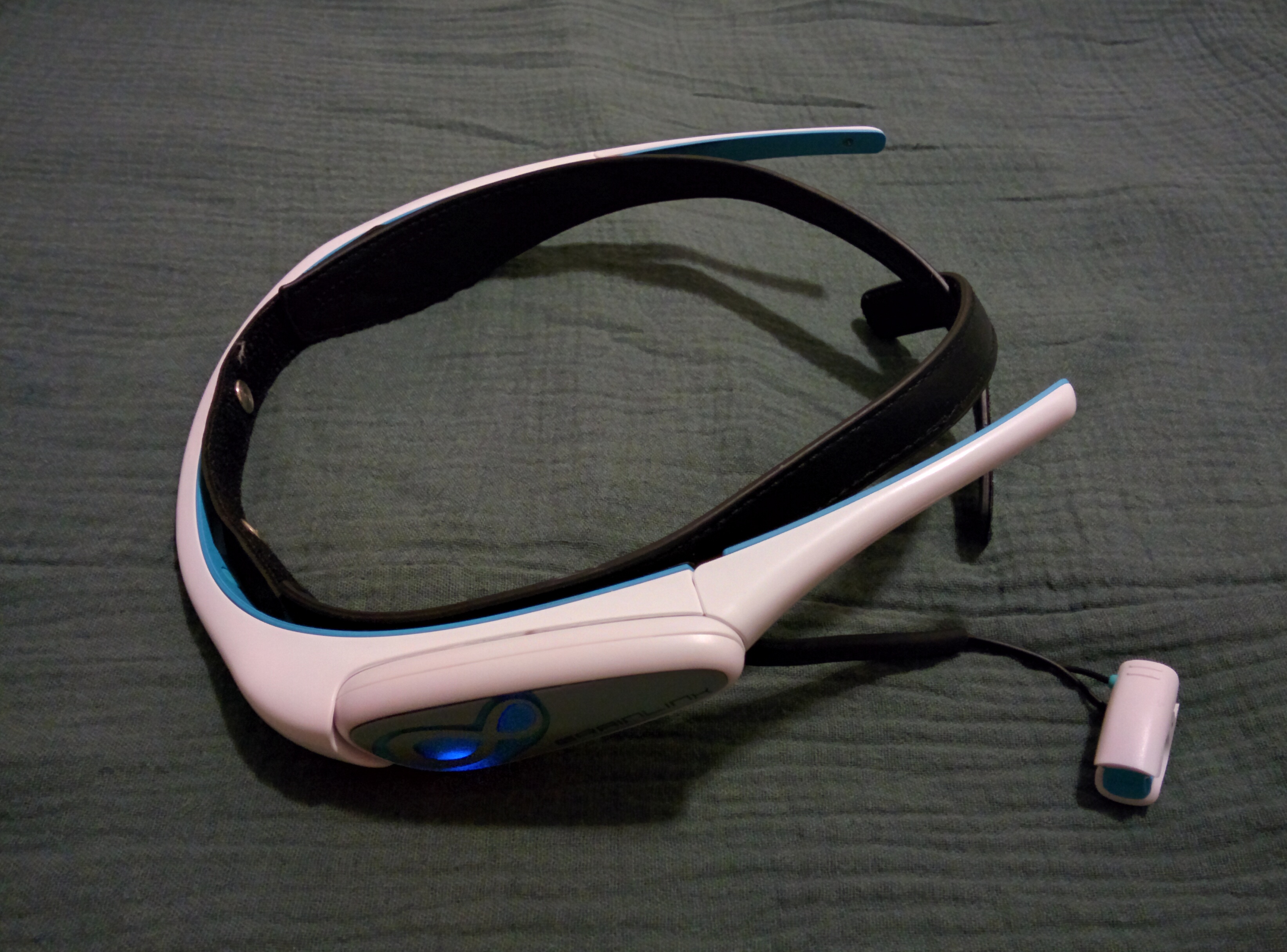
The Macrotellect BrainLink Pro is one of many EEG-based BCI devices built for the consumer market based on newer technologies that utilize dry-cell electrodes that don't require the application of electrolyte paste to electrode-skin contact areas. Macrotellect is based in China and is Neurosky's partner company, so the BrainLink devices utilize the same hardware as Neurosky's MindWave lineup meaning that I would still be able to use the former with OpenViBE. This model was chosen for the project so that the professor could get in touch with the company more easily if necessary without having to deal with a language barrier.
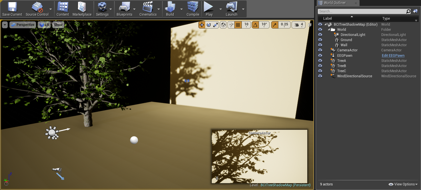
This is how the level was set up within UE4. The wall and ground were just two StaticMeshActor planes; the latter was actually unnecessary as it's never actually seen by the camera, but it was useful during positioning. A CameraActor was set pointing straight at the wall, and a DirectionalLight was created pointing in the same direction so 1-to-1 shadows could be cast. The three trees shown were modeled in SpeedTree and are in roughly the same position, just placed in different orientations to show different branch shadows on the wall. Finally, a WindDirectionalSource was placed to act as a source of wind the SpeedTree models could react to.
↿ Back to top ↾Reading Signals with OpenViBE & the UE4-BCI-Plugin
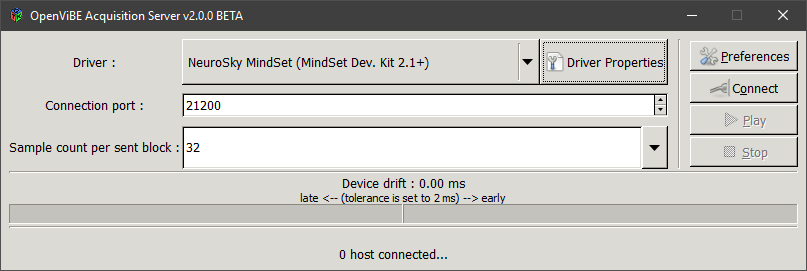
In OpenViBE Acquisition Server, Driver was set to Neurosky MindSet (MindSet Dev. Kit 2.1+) since Neurosky and Macrotellect devices share the same hardware. Your Connection Port would be set to whatever port you'll use within OpenViBE Designer.
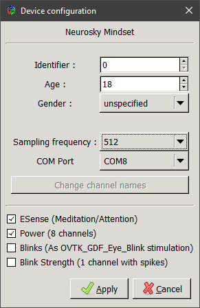
Within Driver Properties (requires your BCI device be on and connected to the computer), Identifier would be set to whatever value you'll be using for that BCI device within UE4. Sampling Frequency can be raised or lowered if you know how frequently your BCI device spits out readings. Our BrainLink Pro only sends signal data once a second (with an intermediate transient data point immediately before each value update), but I left it as its default as it would not affect the setup. Signal channels were activated for BrainLink's ESense readings and brainwave Power channels as I would be using both in the setup.
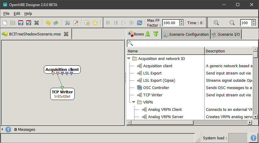
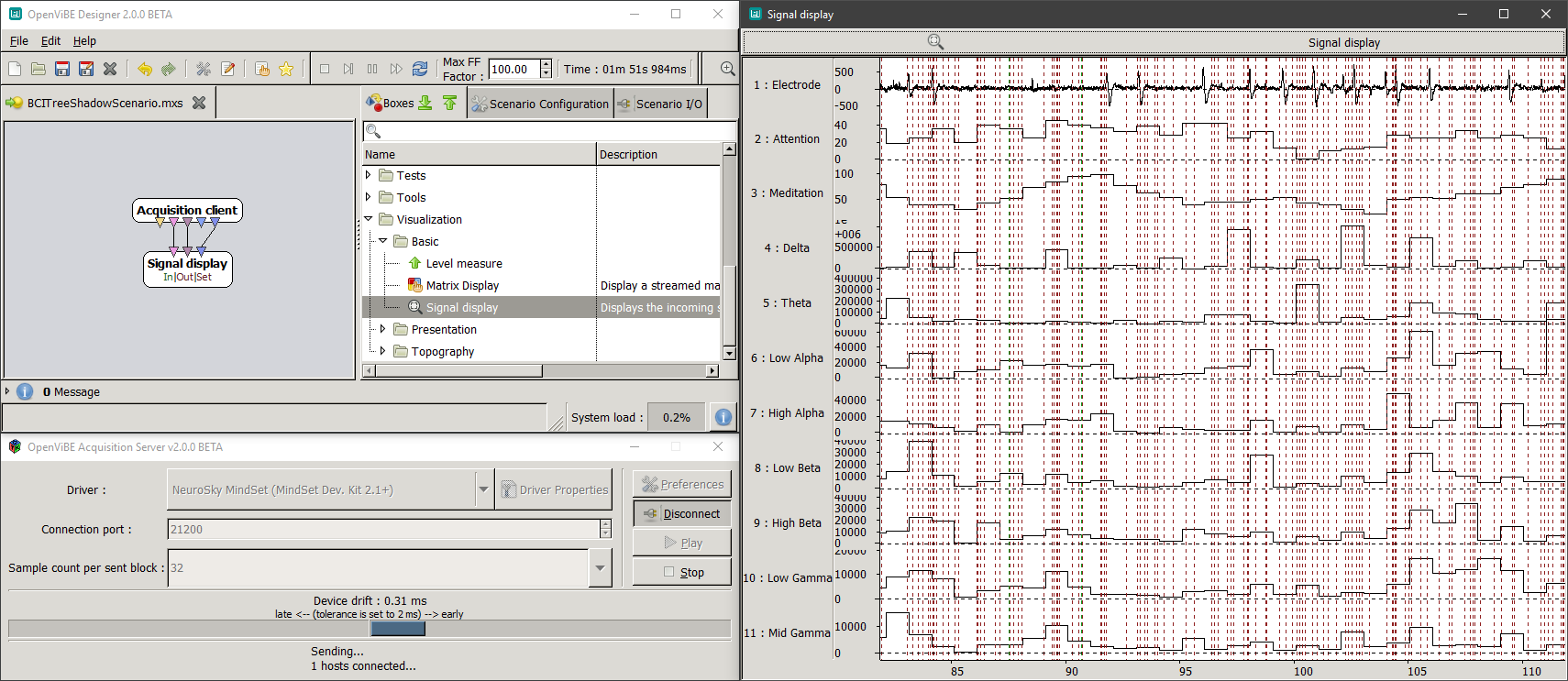
In OpenViBE Designer, an Acquisition client was created, and configured so that its Acquisition server port was the same as our Acquisition Server's Connection Port from before. A TCP Writer (available in both 2.0.0beta and 1.3.0stable, but you will need to show unstable boxes in the latter) was added as well, and its Streamed matrix input hooked up to the Acquisition client's Signal stream output. Its Port is then configured to whatever port will be used for that BCI device within UE4.
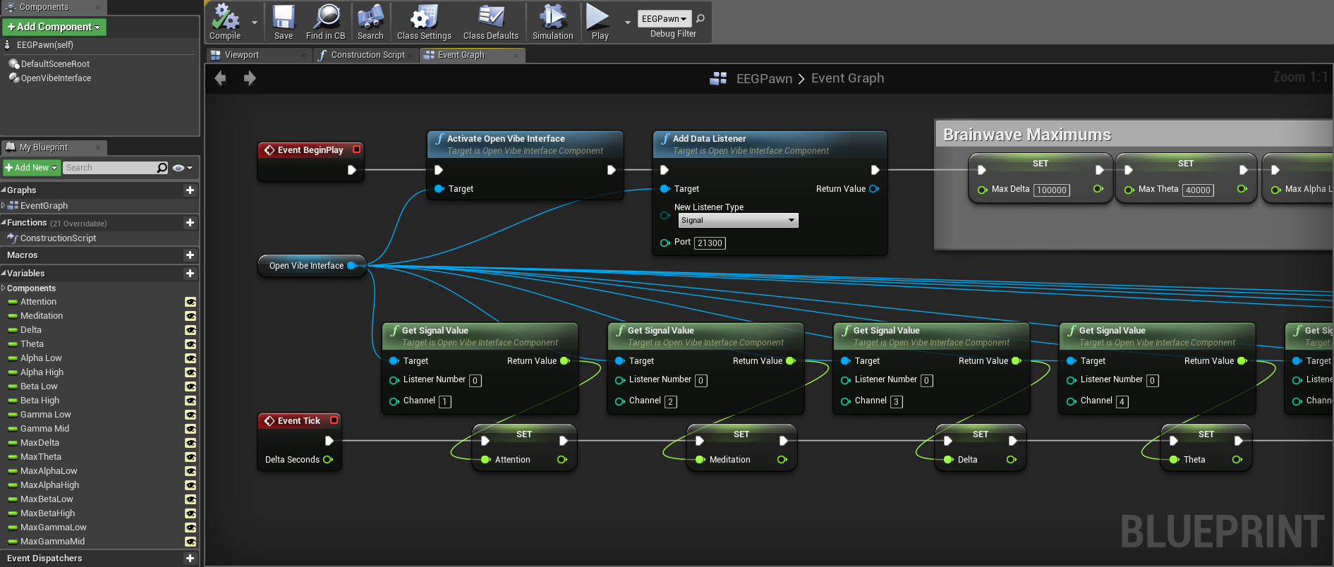
The UE4-BCI-Plugin allows for BCI integration into existing projects by providing components that can be added to project actors such as pawns. Pawns in UE4 are actors that can be possessed by players or AI and receive inputs from a controller. I created a Pawn in my level and added an OpenViBE component to it. In the pawn's Event Graph, on Event BeginPlay I activated the OpenViBE Interface and added a Data Listener to it, changing its Port to whatever was used previously in OpenViBE Designer's TCP Writer. On Event Tick I got all the signal values I wanted from OpenViBE and set them to public variables I created within the pawn. Listener Number is set to whatever was used previously in OpenViBE Acquition Server's Driver Properties Identifier.
Channel 0 for this particular driver was just a general electrode output, which I wouldn't be using for the project. Channels 1 & 2 were the BrainLink's ESense readings, which returned integer values from 0 to 100 (intended to be used like a percentage). Channels 3 through 10 were brainwave power level bands, which don't have any meaningful units according to the Development Knowledge Base:
Typically, power spectrum band powers would be reported in units such as Volts-squared per Hz (V^2/Hz), but since our values have undergone a number of complicated transforms and rescale operations from the original voltage measurements, there is no longer a simple linear correlation to units of Volts. Hence, we do not try to label them with any conventional unit. You can think of them as ASIC_EEG_POWER units, if you must.
The reason we say they are only meaningful compared to each other and to themselves is primarily due to the fact they have their own units as described above. It would not necessarily be meaningful nor correct to directly compare them to, say, values output by another EEG system. In their currently output form, they are useful as an indication of whether each particular band is increasing or decreasing over time, and how strong each band is relative to the other bands.
The values returned had some spikes that reached some pretty high values though, and because I would be clamping the values later on when converting them to color values, I would have to define some maximums, likely on the lower side to make the simulation more dynamic. EEG devices also typically require a moderate degree of training to use properly, and the pool of users that would be trying the devices on at the art show would probably not be too familiar with controlling them at such a skill level. To get some unofficial maximums, I just wore the device myself for a half an hour and used OpenViBE to output signal readings for all power bands to a .CSV file (which ended up being 140MB in size, don't forget to lower your Sampling Frequency). To eliminate outliers I then took roughly the 80th percentile of each range as my maximum, which nicely ended up being a little more than double each band's median measurement. These maximums were also declared in the pawn as public variables.
↿ Back to top ↾Level Blueprint & HUD Setup
This demo requires dynamic shadows, so the first thing I did after placing my trees down was change the Transform Mobilities of my DirectionalLight and all my trees from Static to Movable. This allows for dynamic shadows at the cost of some rendering speed, as opposed to static or cached dynamic shadows.
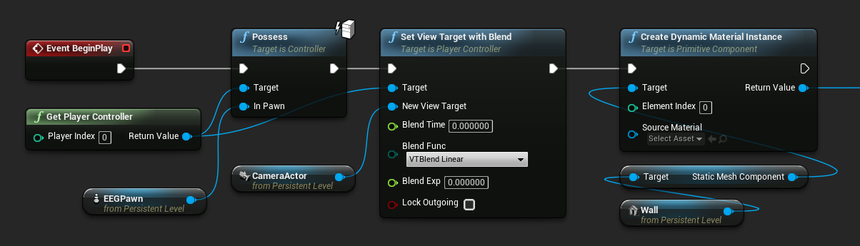
To use a camera placed in a level, it needs to be the view target of a controller, but in order to use a controller it must be possessed first. In the level blueprint, I had my pawn possess the player controller and set the view target to my camera on Event BeginPlay so that the demo would start off looking at the wall using that camera. I also made my wall's static mesh a dynamic material so that I could adjust its appearance based on brainwave signals later on in the project.
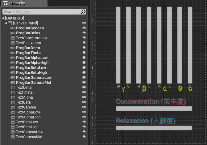
I did want a way for participants to actually see their brainwaves if they or the professor chose to show them, so I rigged up a quick display to do so. In my level I created a User Interface Widget Blueprint (parent class UMG.UserWidget) and threw some progress bars and text onto the designer.
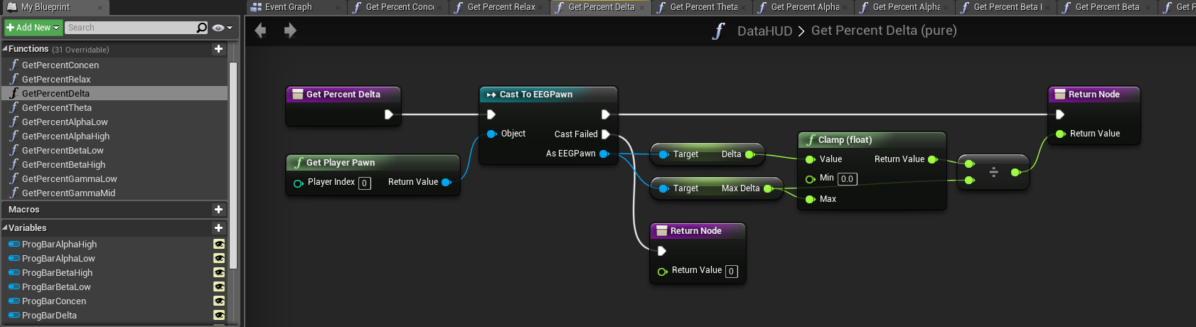
I bound each progress bar's percentage to a function, and within each function a get and cast were made to the pawn I had created earlier so that I could get the necessary signal readings from it. Progress bar percentages are decimal values between 0 and 1, so the two ESense signals were divided by 100 before being returned, while the brainwave power bands were clamped and divided by the maximum values I set for them previously.
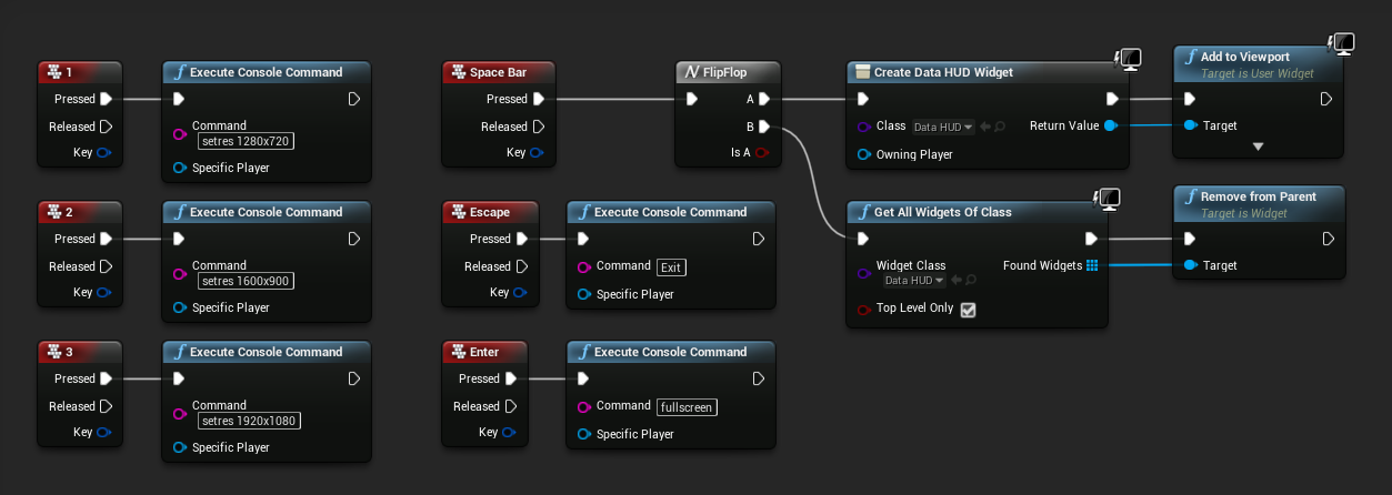
To make it easier for the professor to control the simulation, I also added some keypress events to the level blueprint. Escape would exit the demo, while Enter would toggle between fullscreen and windowed mode. Number keys would be used to switch between resolutions while in windowed mode. To show and hide the HUD, I had the spacebar trigger a flipflop that would create and remove the UI Widget on alternate keypresses.
↿ Back to top ↾Controlling Wind Speed
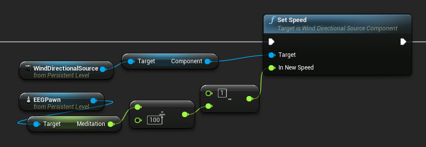
There's not much to say here to be honest. WindDirectionalSource's Speed value can be a decimal value from 0 to 1, so relevant values were clamped and adjusted accordingly before being set on Event Tick. In the above level blueprint snippet, wind speed is set to the inverse of the BrainLink's Meditation readings (the more calm you are, the less windy it will be). Minimum and maximum gusts were also set to 0 for the purposes of this setup so that wind speeds would not seemingly fluctuate randomly.
An unforeseen minor downside to these wind sources is that there seems to be a fixed acceleration and deceleration period when speed values change, and these wind sources will always take a few seconds to smoothly adjust their speed to match the arguments given to it. While the smooth adjustment was desirable (as opposed to abrupt changes in wind speed), as far as I know there doesn't seem to be a way to shorten this transition period or increase the acceleration/deceleration rate.
On a side note, WindDirectionalSource has an additional value labeled Strength, which I initially confused for Speed. Rather than affecting wind intensity, Strength seems to affect how much that wind source is weighted when compared to other wind sources present in the level, e.g. a wind source with a strength value twice that of another wind source will have double the influence on objects compared to that other source.
↿ Back to top ↾Controlling Background Saturation
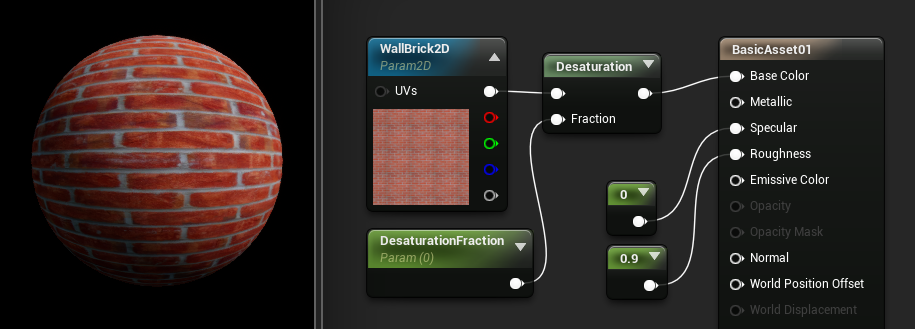
Earlier I made my wall's static mesh a dynamic material so I could have it change as needed over the course of the demo. To start out simple, since it was my first time working with UE4, the first thing I wanted to try was adjusting the wall's color saturation in response to changing BCI signals. This turned out to be pretty easy, as UE4's Material Editor already contains a Desaturation node that can be used to control this property. I plugged it into the wall's material node, and used a color channel and fraction as arguments. The color channel can be a variety of values, such as a VectorParameter if you want a solid color for our material or a TextureSampleParameter2D if you want to use a texture instead (the snippet uses the latter). The fraction is just a ScalarParameter decimal that can be set from 0 (corresponding to full saturation) to 1 (corresponding to no saturation).
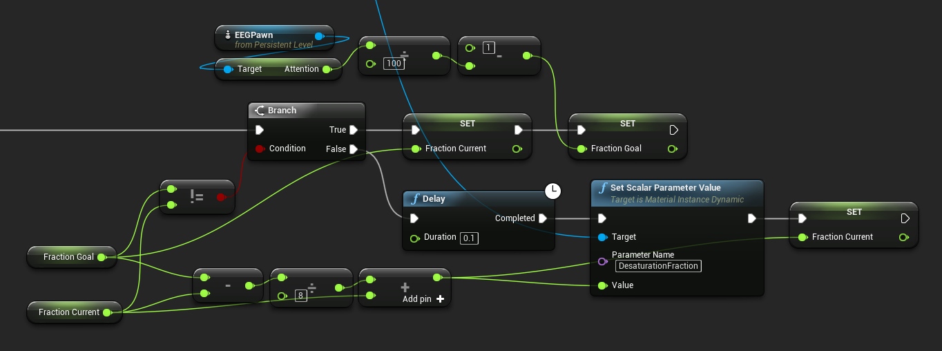
Back in the level blueprint, I created a set parameter node and used the dynamic material instance I defined at BeginPlay as its target. Parameter Name was changed to the name I gave to my fraction parameter back in the Material Editor. The snippet above has saturation influenced by the BrainLink's Attention readings (the more focused you are, the more colorful the background).
Originally, the value of Fraction Goal in the above example was fed directly into the set parameter node like so, which caused changes in saturation to happen abruptly with changes in BCI readings. To help make the transitions between different saturation levels smoother, I created a small delay and had the current fraction value slowly creep towards the goal value. The current value technically never reaches the goal value using this method, but it gets decently close and the on-screen result is much more pleasing to the eye. Using UE4's Lerp node and a custom Event clock, you could likely achieve something similar.
↿ Back to top ↾Controlling Background Color
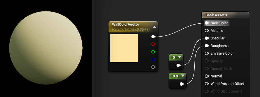
Adjusting saturation turned out to be quite painless, and modifying RGB values ended up being fairly simple as well. Back in the Material Editor I used VectorParameter to go with a solid wall color. If you wanted to use a texture with TextureSampleParameter2D instead, there is a HueShift node that can handle the job for you.
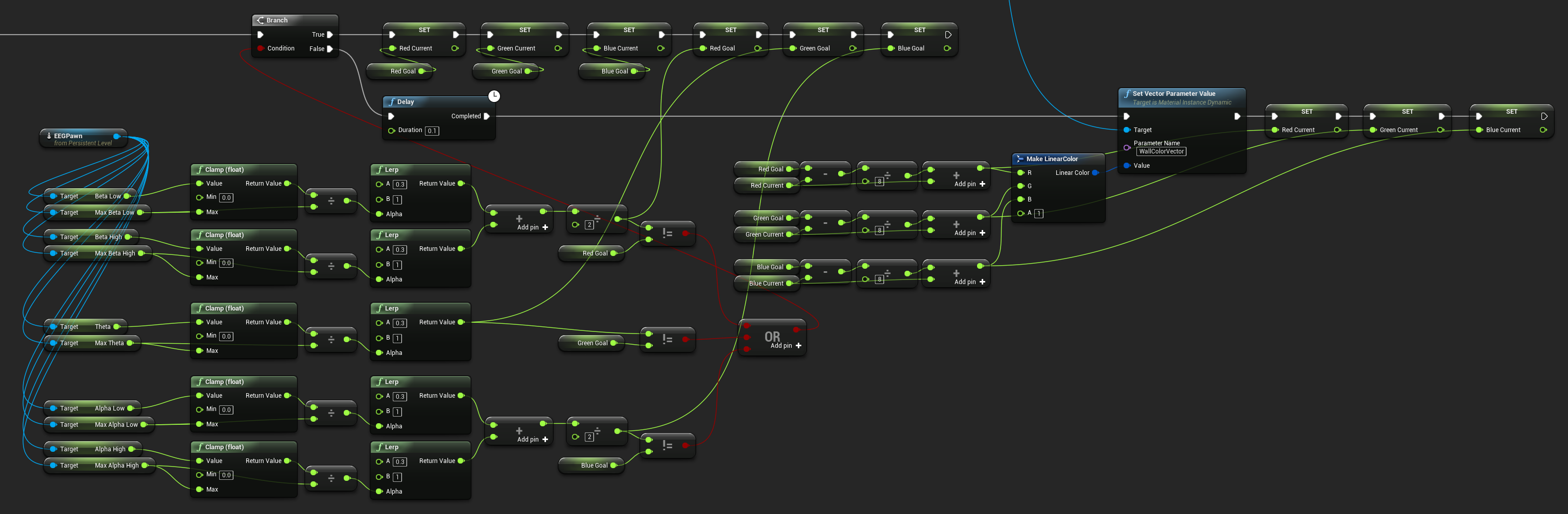
Despite how messy the level blueprint snippet looks, its structure is identical to the saturation control snippet from before. Parameter Name was once again changed to the name I gave to my vector parameter back in the Material Editor. In the snippet, I wanted Beta waves (emitted when consciously alert, agitated, or tense) to influence Red color levels, Theta waves (emitted when in a state of somnolence with reduced consciousness) to influence Green color levels, and Alpha waves (emitted when in a state of physical and mental relaxation that is still aware of surroundings) to influence Blue color levels.
The raw signal data for each power band was first clamped to the maximums I set previously and then linearly interpolated to a value between 0.3 and 1 to use as RGB inputs (0.3 was used as having a baseline background color that was too dark would make the tree shadows hard to see). The BrainLink records two ranges for Alpha and Beta waves, so I just averaged those measurements together for Red and Blue to keep things simple (which probably makes some of this measured data less useful... sorry neuroscientists). The three RGB values are then combined to form a LinearColor struct for use with the set parameter node to change the color of my wall material.
The rest of the mess you see is there to make the transitions between different wall colors smoother, just like with my saturation control blueprint. Current RGB values are slowly adjusted towards the intended RGB values on a short delay.
↿ Back to top ↾Controlling Foliage Quantity
I thought it would be cool if I could find a way to adjust the number of leaves on my tree and have it affected by brainwave signals, and while I did get it working, it's not perfect. My thought process was that it would be very painful to fix individual leaf models to branches and make sure they act realistically with the wind, so it would be easier to instead swap in whole meshes as necessary.
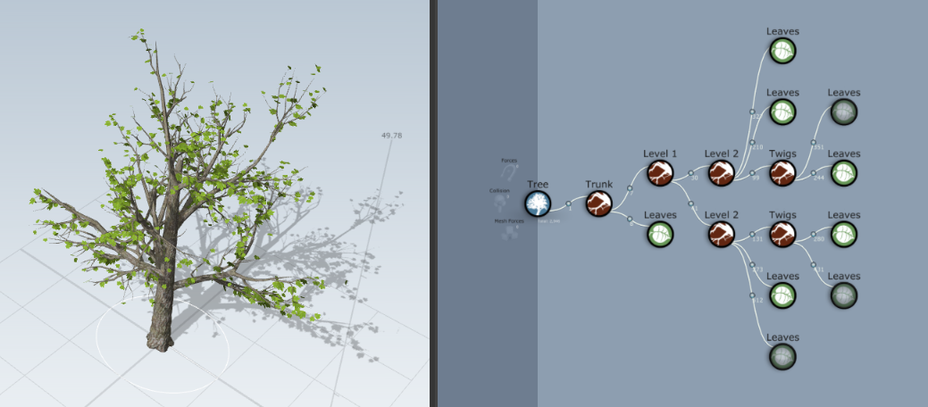
With that in mind, in SpeedTree the plan was to create a tree and model the same branch structure with multiple different leaf densities and export each as a separate mesh as a representation of different brainwave intensities. I didn't want to fill my editor with too many meshes however, so instead I decided to keep the number low and just model 8 different leaf densities (plus 1 bare mesh with no leaves). In the level itself I would use 3 copies of the same tree in different orientations so that each one would cast a different shadow onto the same area of wall.
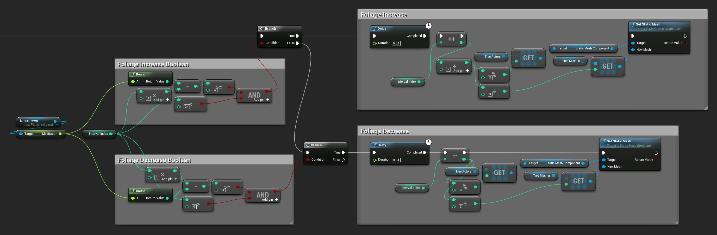
These 3 tree actors were thrown into a StaticMeshActor array, while the 9 different tree meshes were thrown into a StaticMesh array. I also created an integer index value to denote foliage level (with values from 0 to 24 for the 25 levels of foliage I had planned out), and brainwave measurements are converted into this index value to determine how many leaves the tree should have at that measurement. The above snippet has foliage level influenced by BrainLink's Meditation reading (the calmer you are, the more leaves will be on the tree). Trees would have 9 meshes to swap between, starting at mesh 0 with no leaves and ending with mesh 8 at maximum foliage. As meshes would be swapped in abruptly, I also wanted to give foliage changes a more gentle growth and decay. So when increasing foliage, all tree actors would have their meshes swapped out sequentially on a short delay to the level above them before sequentially also making the jump to the next level, and vice versa when decreasing foliage. The table below gives a clearer example of what I mean:
| Index | Tree A | Tree B | Tree C |
|---|---|---|---|
| 0 | Mesh 0 | Mesh 0 | Mesh 0 |
| 1 | Mesh 1 | Mesh 0 | Mesh 0 |
| 2 | Mesh 1 | Mesh 1 | Mesh 0 |
| 3 | Mesh 1 | Mesh 1 | Mesh 1 |
| 4 | Mesh 2 | Mesh 1 | Mesh 1 |
| ... | ... | ... | ... |
| 20 | Mesh 7 | Mesh 7 | Mesh 6 |
| 21 | Mesh 7 | Mesh 7 | Mesh 7 |
| 22 | Mesh 8 | Mesh 7 | Mesh 7 |
| 23 | Mesh 8 | Mesh 8 | Mesh 7 |
| 24 | Mesh 8 | Mesh 8 | Mesh 8 |
I was hoping at first that I would be able to somehow fade these different tree meshes in and out, but sadly, adjusting the opacity/transparency of objects is a task more easily said than done due to the way models are rendered in a 3D engine. The closest you can really get is an effect more similar to a "dissolve" than a fade, which with a tree model would end up rough on the eyes. Straight-up swapping in meshes is done very easily, and is what I ended up doing. However with wind actively exerting forces onto tree models, this results in a slight jolt every time a mesh is swapped with another one, as doing so doesn't preserve the existing positions of the mesh caused by current wind forces. With no wind blowing, this hiccup isn't present, but as wind speed gets higher it becomes more and more noticeable.